
Adding the angle raised the pedal and gave closer to 7"before the floor which increased the master travel to over 1" Not quite at the max available but close enough to have a bit of safety with the fluid volume out. That wound up giving I think less than 3/4 inch of stroke at the master which again by memory only was capabe of something like 1 1/4. The first attempt at a new pedal with increased ratio was a straight but longer arm which as I recall positioned the pedal near the original location heights but maxed at roughly a 4 inch stroke before it touched the floor. Added benefit was being easier to fit the split bellcrank in individual pieces to the space between the firewall and flapper valve in the original air duct. Also wanted to be able to add reinforcement and support plates to the vent area without taking the dash completely apart so that too prevented a one piece already constructed assy.
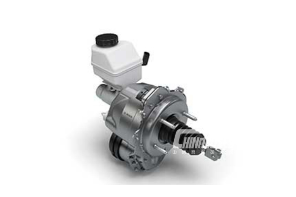
#Ibooster bore install
I was first going to use something like the tri 5 Chevy bellcrank arrangement which allows a master to fit parallel to their firewall under the dash but instead opted for something more open that I could install in pieces to be able to build in stages and have the rods be in a different plane to cross over one another. Raising the pivot allowed for a longer arm to help increase the ratio as well as position the takeoff closer to the area of the vent opening needed for a better input to the bellcrank. Lower than I would have liked but much better than 1:1 original and quite serviceable even with no vacuum. As I recall, my final pedal ratio wound up at just over 3:1.

On my conversion, it has been several years since I did it and don't know where the sketches and details are at the moment. Mounting the Electro master under the dash or maybe with a bellcrank at 90 degrees with a remote fill container in the engine compt might also be an option. Maybe they can measure it according to the attached or similar diagram.Īddendum: There is an interesting reverse swing pedal setup in the post after the 90 degree illustration at the link in the next paragraph. It's the ratio of the distance from the pedal to the pivot axis, to the distance from the master cylinder axis to the pivot axis, measured perpedicular to the master cylinder axis, like in the attached diagram. The position of the bolt on the pedal arm doesn't necessarily have anything to do with the pedal ratio. They could also have issues with balance front/rear, again hard to tell unless one got one. None of these are for particularly large cars, but they did use disc brakes (at least on the front), from what I understand disc brakes require more cylinder volume than drum brakes, but really it's dependent on the stroke and probably not possible to know unless one gets one. The first one is for a Mazda GLC and similar, it has a chance of fitting the Ford Courier booster since that was a Mazda product as well, maybe the booster that naturally fits these is 7" or less as well, haven't looked. Blocking off the air vent and putting it on the firewall is not really a good option for me since I live in a hot environment in the summer, unless I put aftermarket air on the car.ĪBS mentioned that they were measuring the pedal ratio from the pivot point on the pedal to the center of the pad as well as where the bolt is through the pedal arm from the booster to the pivot point. Craig's pedal was similar to how ABS does theirs, however, I haven't heard much feedback regarding this conversion that others have similarly done. My biggest concern with the way that ABS Power Brake makes their system is the fact that the brake pedal looks low to the floor when compared with the original brake pedal in relative location to the gas pedal.

They don't give any information about the stroke though. Here are two master cylinders with 5/8" bore size according to Summit's website.


 0 kommentar(er)
